This page has been designed to provide diagrams of Broadgate ond how it was constructed.
Track Layout
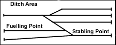
The diagram opposite shows the track layout of Broadgate. The fuelling point is on the left hand side and the stabling point is on the left. The area at the front which is labelled 'Ditch Area' is the place where the 2x1 inch timber was put to create the ditch effect.
Broadgate
Trestles
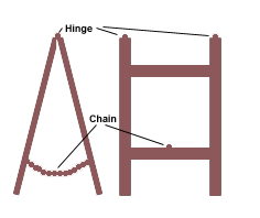
This diagram shows the basic A frame of the trestles. The trestles are held together at the top by hinges and at the bottom by a chain. This makes them collapsable and a lot easier to transport.
The Trestles
The Ditch
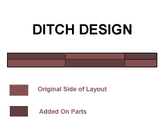
The ditch was designed as described in the baseboard section. It was added to the layout to add some depth. The final effect was very pleasing and has recieved many positive comments.